VIP Mode
This document describes the network topology of OpenELB in VIP mode and how OpenELB functions in VIP mode.
NOTE
- Generally, you are advised to use the BGP mode because it allows you to create a high availability system free of failover interruptions and bandwidth bottlenecks. However, the BGP mode requires your router to support BGP and Equal-Cost Multi-Path (ECMP) routing, which may be unavailable in certain systems. In this case, you can use the Layer 2 mode or, as described in this document, the VIP mode to achieve similar functionality.
- Unlike Layer 2 mode, VIP mode uses the Virtual Router Redundancy Protocol (VRRP) to provide high availability. This approach does not require your infrastructure environment to allow anonymous ARP/NDP packets, making it more widely applicable than Layer 2 mode. However, VIP mode is limited to 255 VRRP instances per network due to the constraints of the VRRP protocol.
Network Topology
The following figure shows the topology of the network between a Kubernetes cluster with OpenELB and a router.
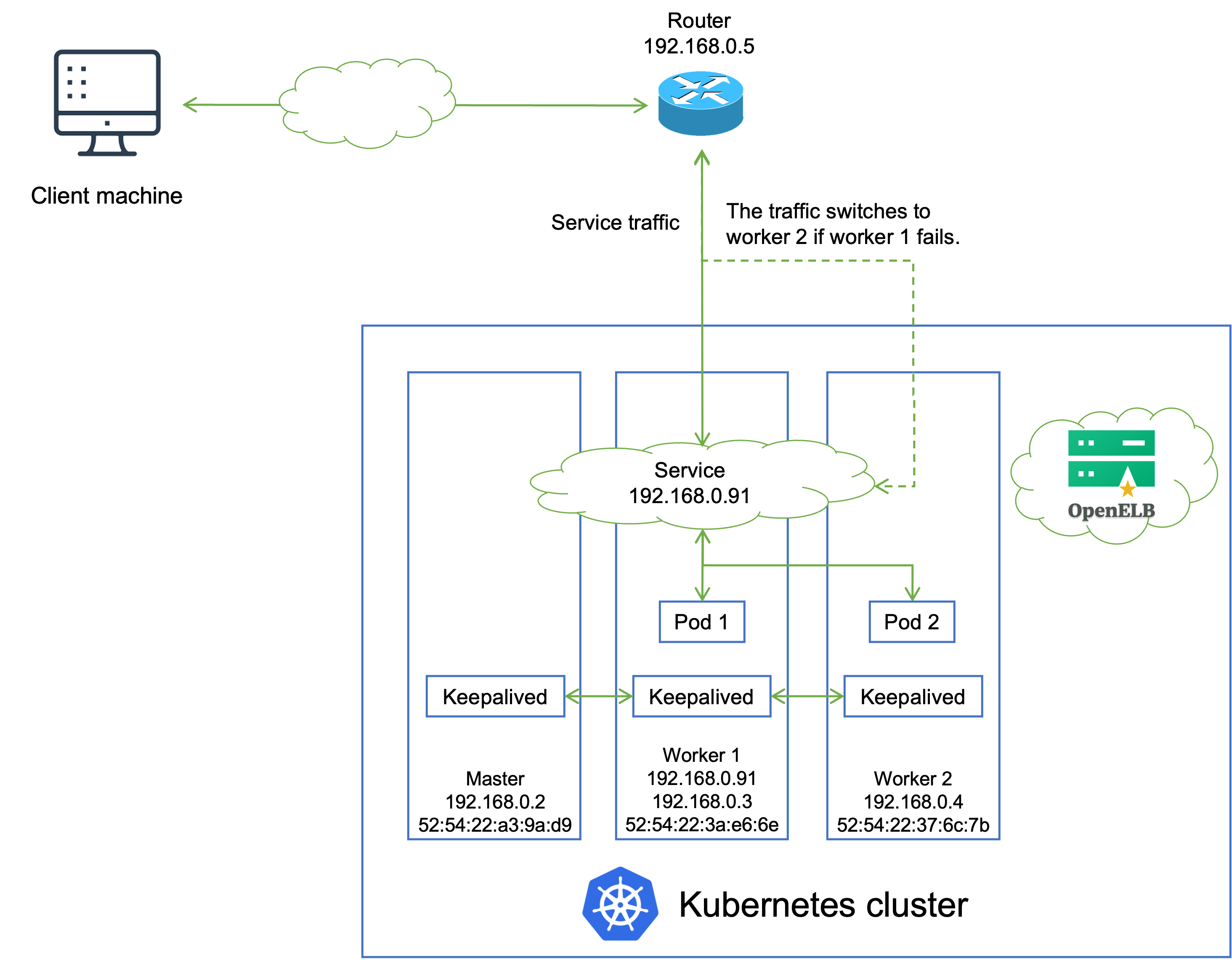
IP addresses and MAC addresses in the preceding figure are examples only. The topology is described as follows:
- A Service backed by two Pods is deployed in the Kubernetes cluster, and is assigned an IP address 192.168.0.91 for external access. The Service IP address is on the same network segment as the cluster node IP addresses.
- OpenELB uses Keepalived to maintain the Service IP address. Keepalived is installed as a Pod on each node of the Kubernetes cluster, and the Keepalived replicas are managed by a DaemonSet.
- The Keepalived replicas negotiate among themselves and elect a leader (worker 1 in this example) to handle Service requests. After that, Keepalived sets the Service IP address on the NIC of worker 1 and maps the Service IP address to the MAC address of worker 1. All devices in the private network can obtain this mapping through the ARP protocol.
- When an external client machine attempts to access the Service, the router forwards the Service traffic to worker 1 based on the mapping between the Service IP address and the MAC address of worker 1. After the Service traffic reaches worker 1, kube-proxy can further forward the traffic to other nodes for load balancing (both Pod 1 and Pod 2 can be reached over kube-proxy).
- If worker 1 fails, the remaining Keepalived replicas reelect a leader (for example, worker 2) to handle Service requests, and the Service traffic switches to worker 2.
NOTE
The VIP mode has two limitations:
- Worker 1 and worker 2 work in active-standby mode in terms of traffic forwarding. When a failover occurs, Services in the Kubernetes cluster will be interrupted for a short while.
- All Service traffic is always sent to one node first and then forwarded to other nodes over kube-proxy in a second hop. Therefore, the Service bandwidth is limited to the bandwidth of a single node, which causes a bandwidth bottleneck.
Generation Rules of VRRP Instance Names
The VIP VRRP instance name is generated using the rule: hash(node list)-interfaceName. Therefore, a new instance will be created if the selected node list or the chosen network interface differs from any existing instance.
The selected node list is determined by the service spec.externalTrafficPolicy, and the chosen network interface is specified by the eip spec.interface. Here is an example to illustrate:
| Service ExternalTrafficPolicy | Selected Node List | Interface Name | VRRP Instance Name |
|---|---|---|---|
| Cluster | node1,node2,node3 | eth0 | hash1-eth0 |
| Cluster | node1,node2,node3 | eth1 | hash1-eth1 |
| Local | node1,node2 | eth0 | hash2-eth0 |
| Local | node2,node3 | eth1 | hash3-eth1 |
Feedback
Was this page helpful?
Glad to hear it! Please tell us how we can improve.
Sorry to hear that. Please tell us how we can improve.