BGP Mode
This document describes the network topology of OpenELB in BGP mode and how OpenELB functions in BGP mode.
NOTE
Network Topology
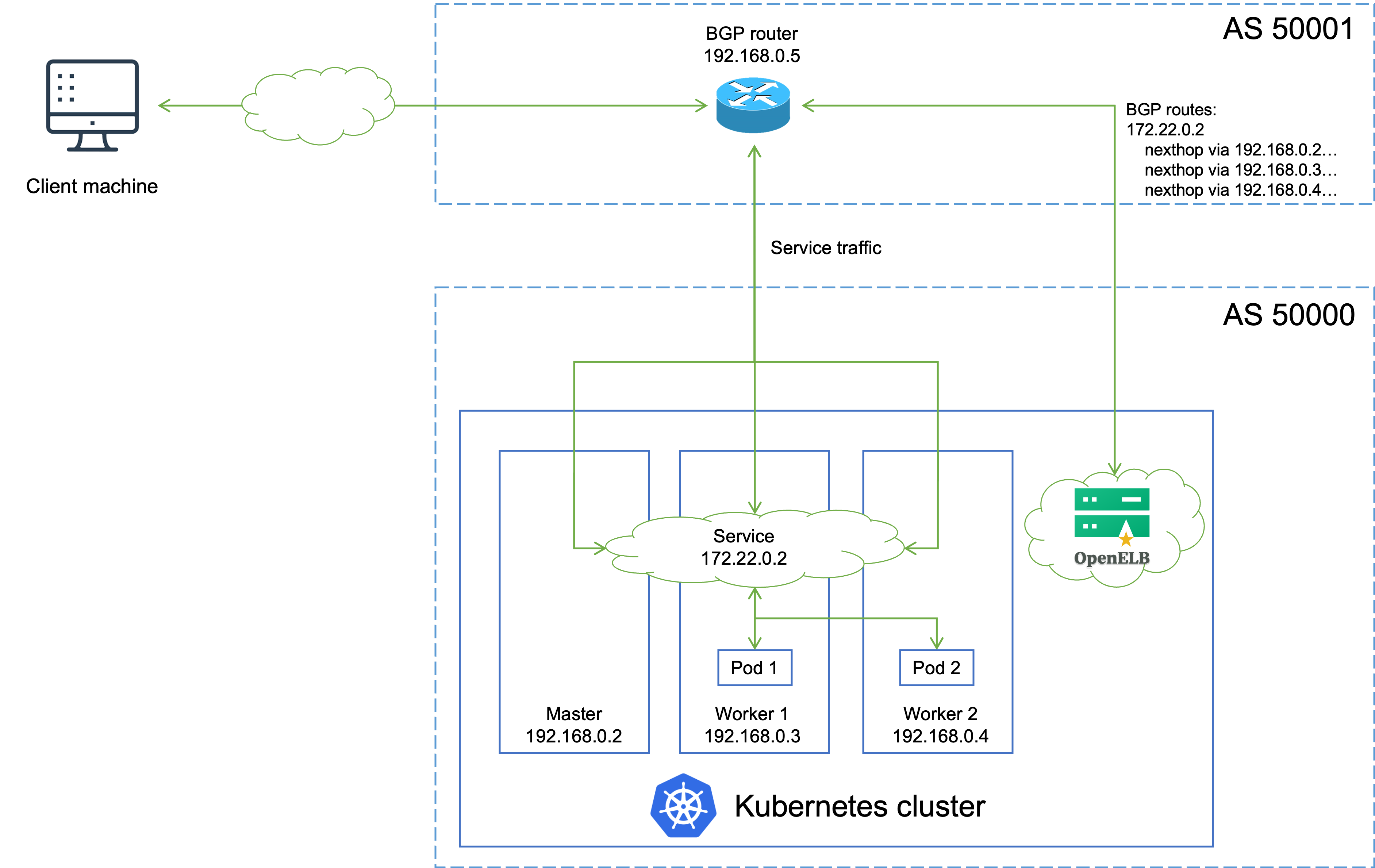
The following figure shows the topology of the network between a Kubernetes cluster where OpenELB is installed and a peer BGP router.

IP addresses and Autonomous System Numbers (ASNs) in the preceding figure are examples only. The topology is described as follows:
- A Service backed by two Pods is deployed in the Kubernetes cluster, and is assigned an IP address 172.22.0.2 for external access.
- OpenELB installed in the Kubernetes cluster establishes a BGP connection with the BGP router, and publishes routes destined for the Service to the BGP router.
- When an external client machine attempts to access the Service, the BGP router load balances the traffic among the master, worker 1, and worker 2 nodes based on the routes obtained from OpenELB. After the Service traffic reaches a node, kube-proxy can further forward the traffic to other nodes for load balancing (both Pod 1 and Pod 2 can be reached over kube-proxy).
OpenELB uses GoBGP (integrated in OpenELB) to establish a BGP connection for route publishing. Two CustomResourceDefinitions (CRDs), BgpConf and BgpPeer, are provided for users to configure the local and peer BGP properties on OpenELB. BgpConf and BgpPeer are designed according to the GoBGP API. For details about how to use BgpConf and BgpPeer to configure OpenELB in BGP mode, see Configure OpenELB in BGP Mode.
Feedback
Was this page helpful?
Glad to hear it! Please tell us how we can improve.
Sorry to hear that. Please tell us how we can improve.